
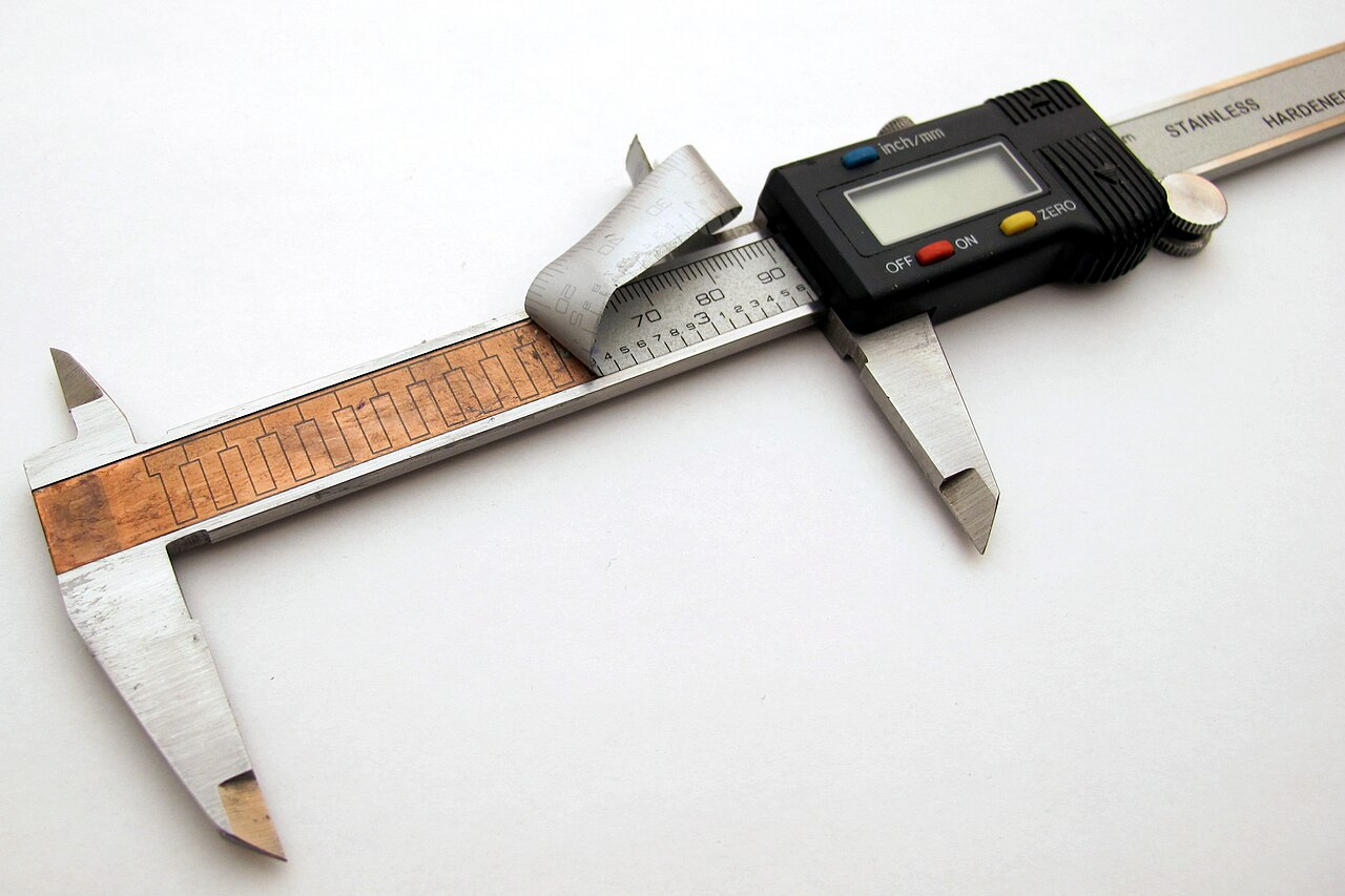
Linear scales for machine-tool readouts are usually bought as sealed units, and their workings are rarely published. A maker who goes by Nick on Hackaday (nichlock on GitHub) has published open-linear-scale, a capacitive linear encoder whose hardware, firmware and tests are all open. It works on the same principle as digital calipers. The project README rates its accuracy at 40 µm (1.6 thou), measured against a Mitutoyo 543-793B-12 at room temperature. The author puts the build cost at roughly $32 before shipping (per the README, as of October 2026). Hackaday covered the project on 22 October 2026.
The README says plainly that the design is still in development. This is an open hardware project you can build from the published files. It is not a product for sale, a pre-order or a crowdfunding campaign.
How the sensor is built
The encoder has two circuit boards. The moving part is a four-layer sensor PCB. The fixed part is a passive two-layer reflector PCB, which carries no active electronics. The sensor's antenna layout is a grid of eight transmitting antennas (the README calls them emitters) sitting under a larger receiving antenna. The transmitted signals couple through the reflector board and into the receive antenna. How strongly they couple depends on where the sensor sits along the reflector pattern.
The gap between the two boards matters. The README specifies about 0.1 mm, set with Kapton. Capacitive coupling falls off quickly with distance, so the spacer is part of the design, not an afterthought. The repository includes an explainer on how the capacitive coupling becomes a position reading, for anyone who wants the theory behind the antenna geometry.
The numbers, as the author states them
- Type: incremental capacitive encoder
- Output: UART
- Accuracy: 40 µm (1.6 thou), measured against a Mitutoyo 543-793B-12 at room temperature
- Scale period: 5.08 mm
- Excitation: 8 emitters driven with a 16-step pattern at 16 kHz, which gives 1 kHz measurement sequences
- Maximum speed: conservatively estimated at 0.6 m/s (untested, per the README)
- Board gap: about 0.1 mm, held with Kapton
- Boards: 4-layer sensor PCB, 2-layer reflector PCB
- Controller: STM32L4 (the repository names the STM32L476RC), with the analog front end integrated in the microcontroller
- Design tools and licences: hardware in KiCad 9 under CERN-OHL-P-2.0; firmware, tests and documentation under MIT
- Estimated cost: roughly $32 before shipping
Two of these numbers need context. First, "incremental" means the encoder measures movement within each 5.08 mm period and counts the periods it passes, not absolute position. The README says it assumes position zero at power-up, so it needs zeroing or homing every time it starts. That is fine on a mill or lathe, where you reference an edge anyway. It is a limitation if your application needs to know where it is the moment power comes on. Second, the 0.6 m/s speed is the author's conservative estimate and has not been tested. It depends on the position-tracking algorithm being able to follow the motion between successive estimates, and nobody has run the scale at that speed yet.
The 40 µm figure also deserves a careful reading. The author calls it a rating: it was read visually from error plots and rounded up conservatively, and the README says the design is not mature enough for a true tolerance stackup. The largest error source is a periodic error that correlates with position.
Why an STM32L4
The controller does more than run the firmware. According to the README, the receive antenna feeds a charge integrator and an anti-alias filter, and that analog hardware is fully integrated within the STM32L4. The README describes no separate signal-conditioning chip. That is a large part of why the parts count and cost are so low.
ST's product page for the STM32L476RC (Wayback Machine snapshot from 3 January 2026) describes it as an ultra-low-power Arm Cortex-M4 MCU with FPU at 80 MHz. It has 256 Kbytes of Flash, plus LCD, USB OTG and DFSDM peripherals. In that snapshot, ST listed the part as Active and available until 01/2035.
The author still finds the STM32L4 harder to source. The README lists less reliance on the STM32L4 as a planned improvement, with a more standard STM32 and a discrete analog front end as the plan. Moving the analog front end onto separate parts would mean redesigning the board and the firmware. The current STM32L4 boards should be treated as a working prototype, not a frozen reference design.
Where it could go
40 µm is the rated figure today. The author started out hoping for 10 µm electrical accuracy, and the README says they are still working towards it. That is a goal, not a result, and no timeline is given. The same list of planned work includes automatic electrical calibration, temperature compensation, layout and mechanical improvements, and absolute position sensing. The README also warns that a capacitive encoder is sensitive to liquids between the boards, and that thermal expansion over long distances matters at these accuracies.
What It Means for Makers
The README says the design targets open-source DRO sensors and digital calipers. Others who could use it are builders of CNC or 3D-printer motion systems who want position feedback, and educators looking for a capacitive sensing example that is fully documented. The main draw is that every layer is open. KiCad 9 sources are released under the permissive CERN-OHL-P-2.0 licence, and the firmware and tests are under MIT. You can fork it, change the period or trace length, and build the result into your own hardware.
What it replaces is a closed scale bought as a finished part. What it adds is a capacitive encoder you can read and modify, with an author who published how the accuracy was checked. Before you build it into a machine, check these limits:
- It is incremental and must be zeroed at every power-up.
- Its output is UART. A DRO head or motion controller that expects a different interface will need adapting.
- The 0.1 mm board gap has to be held mechanically along the full length of travel.
- The 0.6 m/s top speed has not been tested.
- The 40 µm figure was measured at room temperature only, and the author lists temperature compensation as future work. Liquids between the boards are a known sensitivity, so plan for coolant and swarf.
On price and availability: the author estimates the build at roughly $32 before shipping (README, as of October 2026). The design files, firmware and capacitive-coupling explainer are published on GitHub, and you order the boards yourself. The project is in development, and the README says the plan is a more standard STM32 with a discrete analog front end. Anyone building today is building the STM32L476RC version.
