
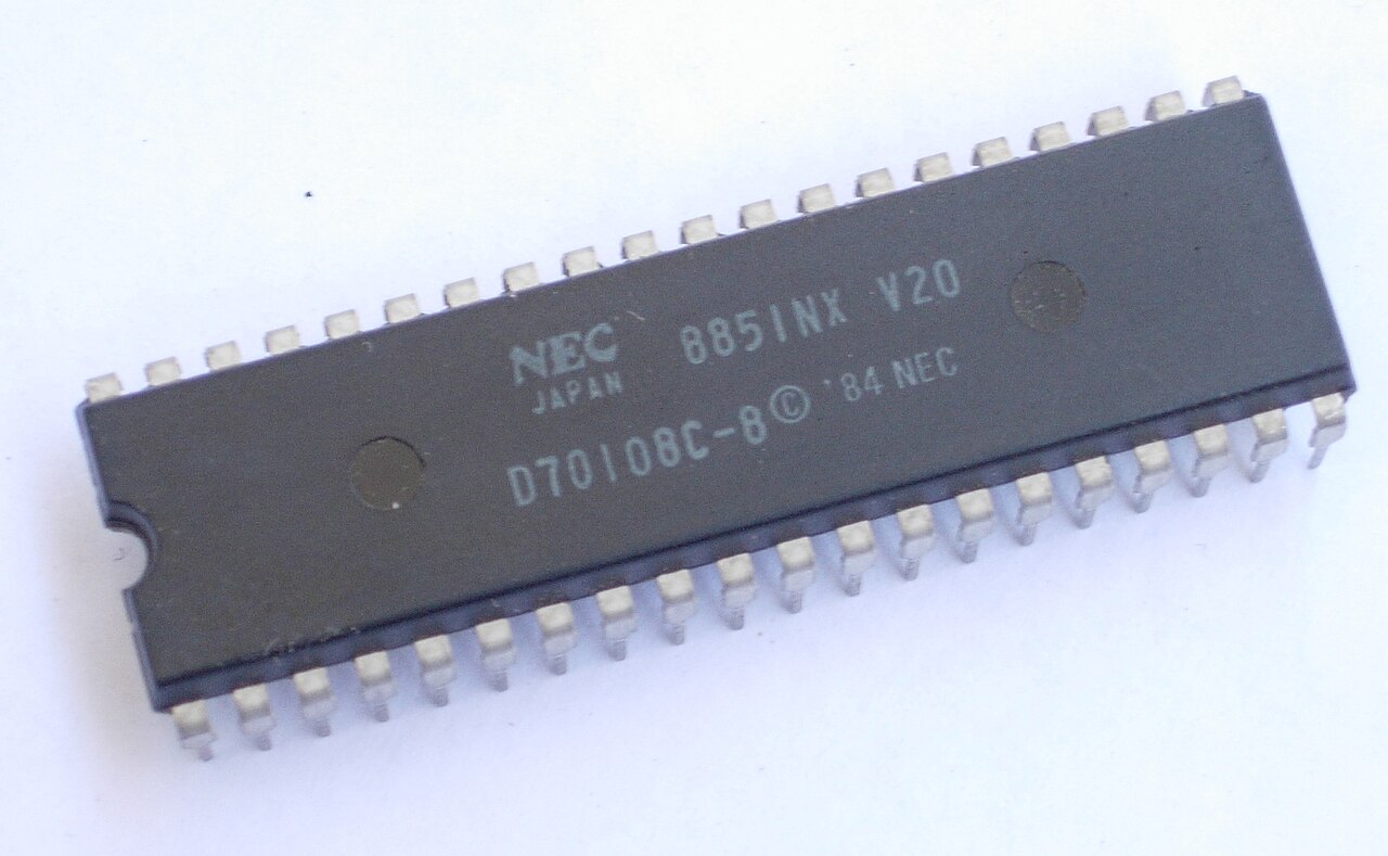
Most retro-PC projects built on modern microcontrollers emulate the CPU. frank-xt8086 does the opposite. The CPU is a real Intel 8086 or NEC V20 sitting in a socket, and a Raspberry Pi RP2350B stands in for everything else on an IBM PC/XT-class motherboard: memory, video, the interrupt controller, the timer, DMA, the floppy and hard-disk controllers, and the serial port.
Mikhail Matveev, who publishes as rh1tech, tagged version 1.00 of the firmware on GitHub on 2026-11-01. It targets what the project calls the xt8086 beta board and is licensed GPL-3.0-or-later. Adafruit's blog covered the release the next day.
How the bus trick works
According to the project README, the 8086 "is not emulated." The CPU fetches and runs its normal bus cycles, driving ALE, RD and WR, and a PIO state machine on the RP2350B answers every bus cycle within a wait state. The README's summary: everything the CPU thinks it is talking to is software.
The RP2350B is well suited to that job. Raspberry Pi's RP2350 datasheet lists 12 PIO state machines across the family, together with dual Cortex-M33 or Hazard3 processors at 150 MHz, 520 kB of on-chip SRAM in 10 banks, 8 kB of OTP, one HSTX block and 24 PWM channels. The B variant is the one with the pins. Table 1 of the datasheet gives the RP2350B a QFN-80 package (10 x 10 mm), no internal flash, 48 GPIO and 8 analogue inputs, against the RP2350A's QFN-60, 30 GPIO and 4 analogue inputs. A design that handles an 8086's shared address/data bus while also driving HDMI, VGA, audio, SD and USB needs a lot of GPIO, which is presumably why the project uses the B. The datasheet also lists the GPIOs as 5 V-tolerant when powered, which is relevant for a design wired to an NMOS/CMOS-era CPU. The project documentation reviewed does not explain how the board handles voltage levels, so read that line as a datasheet spec and not as a statement about this design.
The README says the PC's RAM lives in external QSPI PSRAM. The datasheet gives the RP2350 support for up to 16 MB of external flash or PSRAM on its QSPI bus, plus another 16 MB on a second chip-select. The project materials do not name the PSRAM part or its size.
According to the README, CPU clock frequency can be set to 1, 4.77, 6 or 8 MHz in the firmware's SETUP utility. The 4.77 MHz option matches the original IBM PC's clock.
The emulated chipset, part by part
The v1.00 release notes list the peripherals the RP2350B presents to the CPU:
- Memory: 736 KB of RAM, which drops to 640 KB when an EGA/VGA or Hercules card is configured.
- Video: CGA/Tandy, Hercules and EGA/VGA. The release notes say output goes over HDMI and VGA at once. The README gives the output as 640x480 on HDMI (connector J12) or VGA (J11).
- Audio: PC speaker and AdLib (OPL2), in stereo.
- Core logic: 8259 programmable interrupt controller, 8253 programmable interval timer and 8237 DMA controller.
- Storage: an 8272 floppy controller with two disk images, and an XT-IDE hard disk with one image. The microSD card is also visible to DOS as drive H:.
- Serial and input: a 16550 UART, with a USB mouse presented to the PC as a Microsoft serial mouse.
- Clock: a DS3231 battery-backed real-time clock.
The firmware ships with three pieces of PC-side software: GLaBIOS as the system BIOS, the XTIDE Universal BIOS for the hard disk, and bootOS as a fallback when there is no card. The README places GLaBIOS, an 8 KB image, at 0xFE000.
Using it
The release notes and the Adafruit write-up say floppy and hard-disk images go in a /XT/ folder on a FAT32 microSD card. Pressing DEL at the splash screen opens SETUP. While the machine is running, Win+F11 brings up a drive menu for changing images and Win+F12 opens SETUP.
The firmware is distributed as frank-xt8086-1.00.uf2. The release notes describe two ways to flash it: a Debug Probe, or holding the board's S3 (BOOTSEL) button, pressing S4 (reset) and copying the file to the drive that appears.
The release notes flag one trade-off. The default build has no serial console, because GP44 is used for the right audio channel. Building with UART_CONSOLE=ON brings the console back, but audio drops to mono. Developers who want debug output over the serial console have to choose between it and stereo audio.
Where it came from
According to the README, frank-xt8086 grew out of RP8086, an earlier prototype that ran the same idea on a WeAct RP2350B module wired to a breadboarded 8086. The GitHub repository was created on 2026-09-02, so about two months passed between its creation and the 1.00 tag.
What It Means for Makers
The project is aimed at retrocomputing builders who want real 8086 or V20 silicon running real code, without sourcing and debugging a board's worth of period-correct support chips and ISA cards. The single RP2350B takes the place of the 8259, 8253, 8237, 8272, 16550, the DRAM array and the video and sound cards. It also swaps floppy drives and a hard disk for image files on microSD, and a CRT for HDMI or VGA. For anyone studying the 8086 bus, the source is available to read: the README describes a PIO state machine answering every bus cycle, and the code is published under GPL-3.0-or-later.
It differs from a pure emulator in one important way. The CPU is real silicon running at a selectable 1, 4.77, 6 or 8 MHz, so software executes on genuine 8086-family hardware and not on an emulation core. The project accepts NEC's V20 as an alternative to the Intel 8086.
On availability, the v1.00 firmware has been released, with the release dated 2026-11-01, and source and the UF2 binary are on GitHub. The hardware is a different matter. The project calls it the "xt8086 beta board," and none of the sources reviewed give a price, a seller, an order page or a ship date for it. Anyone who wants to build one today should treat it as a beta hardware design with released firmware, not a product you can buy.
