
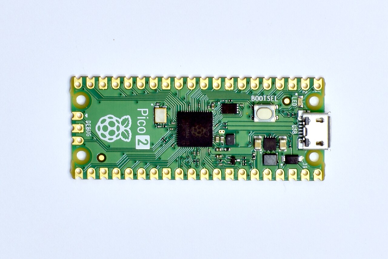
Picotronix, a modular bench instrument built around two Raspberry Pi Pico 2 boards, is now a crowdfunding campaign. CNX Software reported on 28 October 2026 that Thort Werx Pty Ltd of Sydney has put it on Kickstarter, and the maker's own site now says "Now live on Kickstarter". The design gives one RP2350 the job of capturing signals and a second the job of running the display and the wireless link. Front-end hardware goes on plug-in boards the company calls picoPods.
One caveat before the numbers. PinoutFeed did not read the Kickstarter campaign page itself, so we could not check the campaign figures there. The funding goal, reward price, shipping costs and delivery window below all come from CNX Software and are attributed to it. Hardware specs come from the maker's site, from CNX, or from both, and we say which in each case.
Why two Picos?
The architecture is the most interesting part. CNX describes it as a Pico 2 working as the signal processor and a Pico 2 W handling display and wireless. Hackaday covered the prototype in February 2026 and described the same split: one Pico samples, the other handles control, display and communications. The prototype used stacked PCBs in a 3D-printed housing.
The two boards talk over what the maker calls Picogram, a structured data protocol. According to the Picotronix site, Picogram links the two Picos and is also designed to connect the instrument to a phone or PC over WiFi or USB. Hackaday noted that the inter-Pico datagram protocol is documented and that its messages can come from a host computer, so the unit could serve as a test station driven over WiFi or USB rather than only as a handheld with a screen. Hackaday also described the display as optional on the prototype.
The maker also lists "external access to RP2350 state machines" as a feature, which means the PIO blocks are exposed to user code. CNX says the instrument is programmed in MicroPython with PIO access.
The Main Module, spec by spec
The base unit is the Main Module. The maker's page lists a two-channel oscilloscope, an 8-input logic analyser, a frequency counter, a voltmeter and a logic probe, with a 320x240 colour LCD. CNX identifies the LCD as a Pimoroni part. The maker describes the wider instrument as a digital oscilloscope, logic state analyzer, waveform generator and "Electronix Lab". It has two analog expansion ports and one multifunction port for pods.
CNX gives more detail on the front end and capture:
- Oscilloscope: 2-channel DSO. The analog input accepts 3 Vpp or 16.6 Vpp at 1 MOhm. Capture uses the RP2350's 12-bit ADC, with timebases from 5 ms to 10 us/div.
- Logic analyzer: 8 channels, expandable to 14 with a picoPod, at sample rates up to 150 MHz.
- Display: 320x240 (Pimoroni LCD, per CNX).
- Power: USB, a 9-12 V plug pack, or 4 AAA cells. The maker's page lists USB-C or four internal AAA cells and does not mention the plug pack.
CNX gives no analog bandwidth figure for the built-in scope channels. The maker's page does: it lists a 10 MHz bandwidth to the RP2350, and says the system uses the RP2350's native ADC for lower-frequency signals. In a February 2026 forum post the creator put the ADC at 500 kSPS and described reaching 10 MHz on periodic signals by sub-sampling. Those are the maker's own figures, not independent measurements. For faster analog capture, the design relies on pods.
The picoPods
The maker's site says pods configure themselves when plugged in. CNX lists the following modules:
- Single-ended analog: 500 mV, 1 V, 2 V and 5 V windows within a +/-5 V range, and up to +/-50 V with a x10 BNC probe.
- Differential: 2 Vpp, with +/-25 V common mode.
- Wave-05: a 12-bit R2R DAC waveform generator covering 10 mVpp to 3.3 Vpp, with +/-5 V offset.
- Logic state analyser: 12 bits at 150 MSPS, arranged as three 4-bit ports, with selectable 1.8, 2.5, 3.3 and 5 V logic levels.
- MSO-12: a 100 MSPS 8-bit ADC, plus 8 logic inputs and a 4-channel 12-bit serial ADC.
- ADC-100: dual 100 MSPS ADCs. On a stock 150 MHz RP2350, CNX says these reach up to 75 MSPS on one channel or 50 MSPS on two.
The ADC-100 figures matter. The ADC chips are rated at 100 MSPS, but at the RP2350's stock 150 MHz clock the Pico can only take samples at 75 MSPS (single channel) or 50 MSPS (dual), according to CNX. The maker's page agrees, and adds that single-channel 100 MSPS needs the RP2350 overclocked to 200 MHz, which it says is optional and at the user's own risk. Buyers comparing it with entry-level USB scopes should use the lower numbers.
Software: MicroPython, in stages
Picotronix is described as MicroPython-programmable throughout. The maker's site says software is being rolled out in stages. CNX reports that a PC emulator is planned. In a February 2026 EEVblog forum thread, the creator (posting as picojohn) described the company as a "tiny Aussie start-up (two greybeards - well and truly)". He wrote that it had spent 14 months designing and prototyping the instrument, with capture on the Pico 2 and display and control on the Pico 2 W, which uses WiFi to reach a phone or PC.
Is it open source?
The sources disagree here, so the safest answer is "unclear".
- The maker's site calls Picotronix "an open architecture, MicroPython programmable modular instrument".
- The creator's EEVblog post refers to an "open source architecture written in Micropython".
- Hackaday wrote in February: "This isn't an open-source project, but it is quite well-documented."
- CNX says it is unclear which part of the project is open-source, since there is no mention of a hardware or firmware release. It adds that the Kickstarter page indicates part of the code will be open-sourced.
"Open architecture" can mean a documented protocol and user-programmable MicroPython without any licensed design files or source code. Until Thort Werx publishes schematics, firmware and a license, buyers should assume they can program and extend the instrument but cannot necessarily rebuild or modify its hardware and firmware freely.
What It Means for Makers
Picotronix is aimed at hobbyists, educators and embedded developers who already work with the RP2350 and want a low-cost instrument they can script. Its main selling point is not raw performance. You can write MicroPython for the instrument and reach its PIO state machines, and the Picogram protocol is designed to let a PC or phone drive it, although the maker says that software is arriving in stages. That could make it a candidate for automated test fixtures and for classrooms, where students could see both the signal and the code that captured it. That is our inference, not a claim from the sources.
Specs should be read with care. The built-in scope uses the RP2350's own 12-bit ADC with a fastest timebase of 10 us/div, per CNX, so out of the box it is limited by that ADC rather than built for fast signals. Faster analog capture requires the MSO-12 or ADC-100 pods, and the ADC-100's practical ceiling on a stock clock is 75 MSPS single-channel or 50 MSPS dual. Fast digital work is better covered: the logic paths reach 150 MHz / 150 MSPS, and the logic state analyser pod supports 1.8 V to 5 V logic levels.
Status: crowdfunding, not shipping. According to CNX, the Kickstarter goal is A$10,000 (about US$7,000). The Main Module reward is the equivalent of US$134 at launch and includes a cable set. Shipping is A$20-40 to Australia and US$21-42 to the rest of the world, with deliveries expected to start by March 2027. CNX did not list prices for individual picoPods, saying only that they cost extra, and we could not confirm any campaign figures on Kickstarter itself. As with any crowdfunded hardware, the delivery date is a target, not a promise, and the software roadmap is still being rolled out in stages.
Sources
- Picotronix (creator site): Modular Pico 2 Oscilloscope and Logic Analyzer
- CNX Software: Picotronix modular oscilloscope and logic analyzer features two Raspberry Pi Pico 2 boards (28 Oct 2026)
- Hackaday: A Higher-End Pico-Based Oscilloscope (2 Feb 2026)
- EEVblog forum: Picotronix creator thread (11 Feb 2026)
